

The contract for providing comprehensive project management services including design review, procurement support, construction supervision, ...
LASTEST NEWS
CONTRACT / PROJECTS
Contract/projects
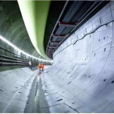
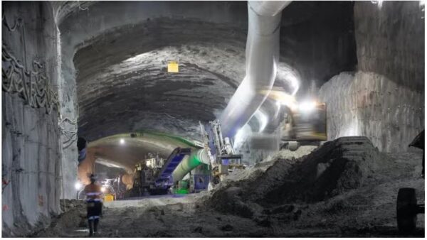
Before building the Northern Tunnels, a second precinct for Australia’s River Torrens to Darlington (T2D) Project has been established. With the aim of ...

Contract/projects
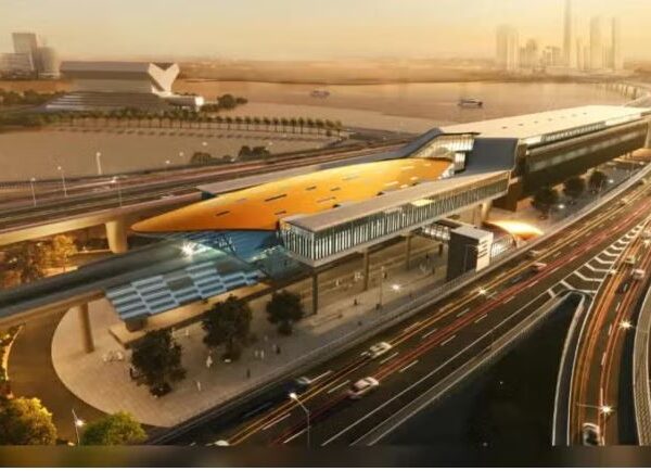
During the contract that the German manufacturer Herrenknecht has concluded with Gamuda, it is to supply three TBMs for Taiwan’s Kaohsiung Metro Yellow ...
Contract/projects
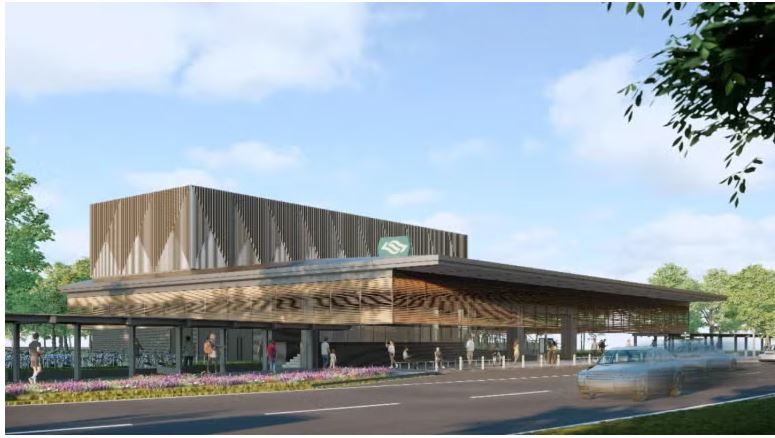
In order to advancing the Phase 2 of the Cross Island Line (CRL), civil construction works has been started by Singapore’s Land Transport ...
Contract/projects
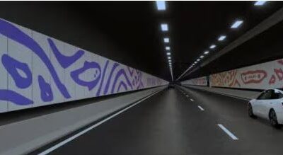
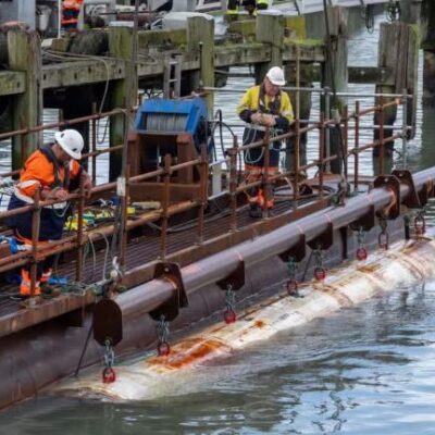
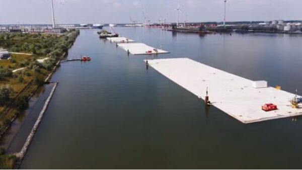
Through the North Sea, the eight elements for the immersed tunnel have been towed over a 111km journey from Zeebrugge to the Scheldt ...
Contract/projects
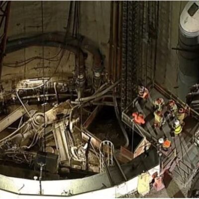
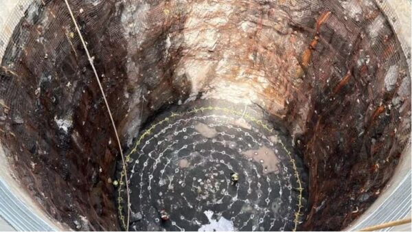
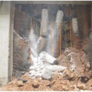
Over than 50% of shaft excavation on the Ellicott City North Tunnel Project in Maryland, which are the 49m-deep shafts and are due ...
Contract/projects
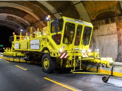
While there is a halt in tunneling of Sydney’s M6 motorway in May, its design and construct contractor has agreed to continue some ...
Contract/projects
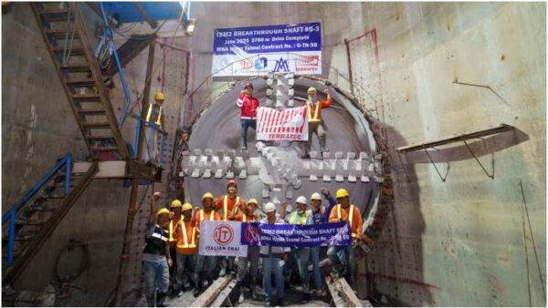
Following that on June 23 a 4.39m-diameter Terratec EPBM has broken through on the Ninth Ninth Bangkok Water Supply Project in Thailand, it ...
FEATURES


0 %
