Microtunnelling can save costs, surface disruption and inconvenience to the public, while the distances that can be covered are increasing. Julian Champkin looks at a 5km project in Canada and asks whether the technique can stretch even further.
The York Region municipality, north of Toronto in the Canadian province of Ontario, needed a new sewer. Almost all communities in the region with force mains – which means the flow is maintained by pumps rather than by gravity – have them twinned; two pipelines running side by side, so that when one is due for inspection, maintenance or repair it can be closed and emptied and the workload taken by the other. But one force main has just a single pipeline.
It dates from 1984, and though it has been maintained as fully as possible, it has not been inspected since it first started operating 36 years ago. Any leak or failure could turn into a major problem. Hence the York-Durham Sewage System force main twinning project: 5.1km of microtunnelling plus a short section of cut and cover to run alongside the existing sewer. The project includes changes to the Newmarket and Bogart Creek sewage pumping stations to improve the system. The CA$110.6m (US$83m) project is billed as “significant and urgent”, will improve the town of Newmarket’s wastewater system and is being led by the York Region municipality.
The microtunnelling work has just been successfully completed by Ward & Burke. The company, which is headquartered in Ireland with offices in Canada, the US and the UK, specialises in water and wastewater infrastructure.
Within Canada and the US, the company focuses on the design and construction of microtunnels and has completed several similar projects nearby, including the CA$41.4m (US$31.1m) East Brampton Trunk Sewer project, which involved constructing concrete caissons and more than 5km of microtunnels in Brampton, Ontario.
On the York-Durham project, breakthrough on the last tunnel came this summer. Permanent chamber construction and mechanical installation is currently in progress, and project completion is scheduled for December 2021. All the microtunnelling drives were completed successfully in less than a year.
The route is predominantly urban, and passes below parks and major streets, under 11 river crossings, and obliquely under three railways. Cut and cover would have caused major traffic disruptions for many months.
““It was the ground conditions, alignment, and depth that dictated we use microtunnelling” said Ward & Burke Director John Grennan. The twinned forcemain alignment was specified to be constructed using microtunnelling methods over approximately 5,040m, with open-cut installation used for approximately 630m. A Ward & Burke value engineer proposal increased microtunnelling distances on the project to approximately 5,576m with final microtunnel drive lengths of 800m, 731m, 501m, 641m, 821m, 950m, and 1132m.”
Those are longer distances for microtunnelling. “Our average drivelength for microtunnelling is around 500m,” says Grennan. “The fifth drive of 1,132m, is in fact the longest microtunnel drive that has ever been achieved in Canada. Breakthrough on that section came on 8 June 2020; the previous record of 950m had been set on the same project just four days earlier, and had broken into the same reception shaft.”
An Established Trenchless Method
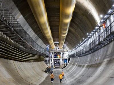
Microtunnelling is now a standard technique. A cutterhead – essentially a TBM in miniature – is placed into an excavated shaft and is pushed forward by jacks pressing against the rear of the shaft. A 3m or 4m length of pipe, generally of concrete, is pushed in with it. When the jacks have reached the end of their stroke they are pulled back, a second length of concrete pipe is placed between the jacks and the previous length, and the jacks are reactivated, pushing both of the lining sections, and the cutterhead, further along the route. The process is repeated, pushing the cutterhead and more and more sections behind it, until the destination has been reached.
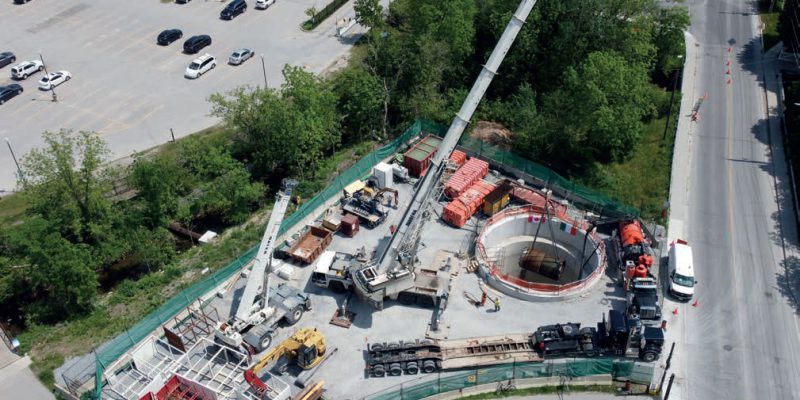
Its obvious advantage is that surface disruption is kept to a minimum. For this project eight shafts were sunk in total, and almost the entire operation was carried out from those. The largest shaft had an outside diameter. of 13m They were lined with reinforced concrete and no de-watering was needed. Work areas were enclosed with three-metre-high solid fencing to minimise disturbance and noise. Noise measurements were taken before commencement, and noise and vibration were monitored continuously during construction.
Clearly the longer the tunnel, the more pipe sections have to be pushed, and the greater the frictional forces that must be overcome between the soil and the linings. Ward & Burke’s kilometre-plus of microtunnelling is thus no small achievement.
“We took a number of measures beforehand” says Grennan. “We installed a 10kVA power supply system for the 1,132m drive, to overcome the volt drop over the greater distance.. We took special care with the planning. Overall we paid particular attention to lubrication and laid three separate lubrication pipes up the tunnel.
“There was changing ground during that drive” says Grennan. “It was very soft clay at the start, then changed to dense silty glacial till with 2-3in [50-75mm] cobbles and some boulders, so it wasn’t doing us any favours. That, too, was an incentive for paying special attention to lubrication.” The water table itself was on average around 12m above the tunnel centre-line.
Intermediate Jacking Stations
A technique commonly used in longer-distance microtunnelling is the installation of intermediate jacking stations to increase total jacking-force capacity: special lengths of pipe with their own jacks are incorporated in the tunnel at strategic locations instead of the standard pipe sections, and are used to overcome high friction resistance by pushing the tunnel forward in sections rather than from the shaft main jacks only. “On that longest drive we installed five sets of intermediate jacks, preparing for high frictional forces that we would need to overcome” says Grennan. “In the end we did not have to use any of them. We made every preparation for a Doomsday scenario that did not happen.
Overall, four TBMs were used across the project. All were remanufactured Herrenknecht AVN slurry machines; outside diameters were 2,108mm for two of the drives, 1,549mm for one drive, and 2,286mm for the remainder. In the record-breaking longest drive the machine was an AVN1800 with an SLS system from VMT to navigate a horizontal curve of 500m radius over a distance of 228m and a very flat continuous grade of 0.02%. The most powerful machine delivered 762kNm torque at the cutter head during the longest drive.
Jacking pipes were supplied by Ontario-based Decast, ASTM C76 Class V, with ASTM C361 joints. They were uncoated. “They were heavily reinforced; they can take huge jacking force, up to 2,000t.” In the end, despite the distance, the jacking force needed was never excessive: the jacks on the long drives were capable of 1,800t, but that force was never needed. “We actually used very low jacking forces” said Grennan.
The fourth 950m drive, though not the longest, was perhaps the most interesting in that an airlock was fitted. This is unusual in microtunnelling. “It was specified by the consultant, GHD. It was a significant length drive, with high water pressure of 1.4bar on average. So the engineering design team felt that an airlock would be advisable in case wear on the cutterhead became an issue. Without one we would not have been able to carry out a face refurbishment.
“They left details of the design to us. We worked with Herrenknecht, who of course have experience of airlock for larger-bore machines, and with a local company ASI Marine who do a lot of construction work on hyperbaric systems offshore. We asked them to design and make an airlock for a microtunnel and submitted it to the Ontario Health and Safety body for approval.
“We used a mixed-ground cutter head, with tungsten carbide tips; and because of that it turned out that in fact no disc changes were needed so we did not in the end have to use the airlock. So again, as with intermediate jacks, we planned for a doomsday scenario which did not in the end happen. Even so, it was interesting to have done it and to observe how an airlock could be applied to smaller diameter tunnelling.”
And then, along came the coronavirus pandemic. “We launched the 1,132m tunnel in mid-March; and with 200m of tunnel completed the pandemic shut us down for three weeks. We came back pushing the machine, expecting to meet large resistance, but once it was moving again the jacking forces went right back down to where they had been before. I put that down to the quality of the bentonite lubrication. It stayed in the annulus for a good long time, and once the jacking re-started we were just reshearing the bentonite.”
They were using a Herrenknecht automated lubrication system pumping a Baroid Bore-Gel and water mix at 1.6 to 2.2 times the theoretical annulus. Centre-line depths varied from 5.5m to 22m. Grades throughout were low and fairly constant, between +1.56% for the initial section to -0.61% on the fourth drive. All the sections involved curves as well as straight parts. The sharpest radius involved was 435m.
Navigation was by VMT SLS LT guidance systems. “It gave us no issues. In softer ground the operators had to put in significant amounts of input to stay on grade, but there were no real problems. It was really a model drive,” says Grennan.
One might have expected slower progress with increasing length of pipe being pushed but that was not the case. “The rate of progress stayed very constant – there was no slowing with distance.
That drive took 22 working days, at 24- hour working, so 44 shifts from launch to breakthrough. It was a very even output. That was working five days a week. We were so confident that we gave the guys Saturdays and Sundays off.” Completing 1,132m of tunnelling in 22 days works out at 51m per day.
So is this towards the theoretical or practical distance-limit for microtunnelling? “There have been longer distances microtunnelled,” says Grennan. “The world record is over 2km, which was achieved in Mexico two years ago. We at Ward & Burke did a 1,250m microtunnel in the UK, also two years back. So, one kilometre and more is possible for us, 1.5km is achievable with good planning and control during construction, and the technology will allow 2km. After that, the technology starts to become less efficient and the technical obstacles to overcome dramatically begin to increase.
“One of the limiting factors is pipeline diameter. For long drives, we need to be able to walk the tunnel to survey our work, or if we need to change a cutterhead tool or maintain or repair the machine – though those did not in this case arise, accessibility is critical. The Ontario H&S people require at least five people with rescue training on-site at all times. We chose to have our staff officers trained for that, to avoid the need for a separate team onsite. We did that participating with the local union; it was good to have our guys in on it. They had refresher practice sessions once a month, walking along the tunnel to the cutter head. Some of our inside diameters were 1.8m, some were 1.65m; you can walk in that, but you need to keep your head down. So, a lesson from that is that for a longer drive you want a larger diameter.
“Also for longer drives you want more thorough planning and more sophisticated equipment, such as advanced lubrication plants: you will want to be sure of geology and such things. We are looking for opportunities to go longer. But it may be that the main limitation is lack of demand. Clients generally want manholes or access points along the route, so these can be used as reception shafts, meaning there is no necessity for very long uninterrupted drives. But we can certainly do them if they are wanted. When we finished our longest drive on this project, we had a site meeting and agreed that we could have gone on for another 400m with no problem. It is not often at the end of a job that you wish it had gone on longer.”
Source: Tunnels and Tunneling


